CASE STUDY: Laser robotic station

21. 1. 2021

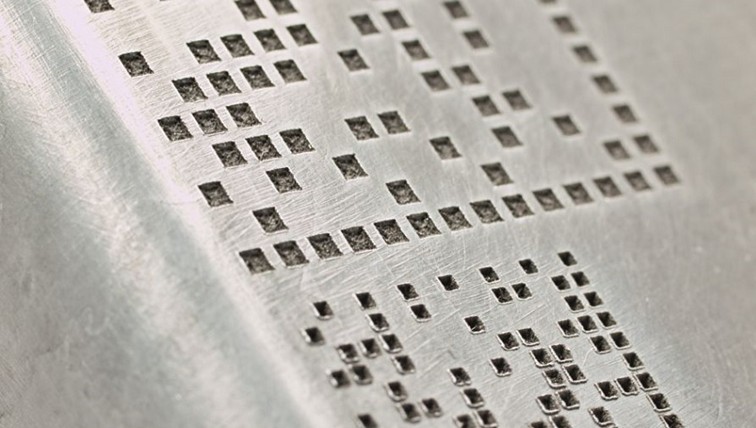
Around mid-2020, we were approached by ZF Automotive Czech s.r.o. regarding a project for laser relabeling of engine components. However, the assignment itself presented several challenges. In terms of laser application it is necessary to rewrite the original marking, the form of which can vary, and above all to apply this processing principle to hundreds of different components in various designs.

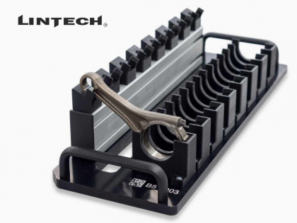
The range of processed components is really large and at the same time very varied. Individual components differ not only in physical dimensions, weight, material, but also in the position of the original marking.

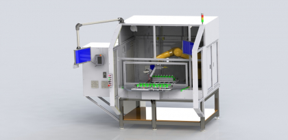
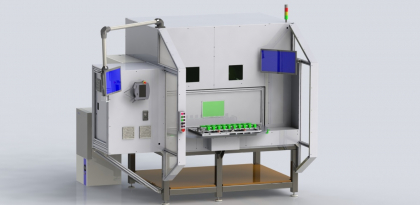
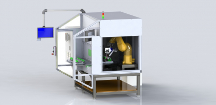
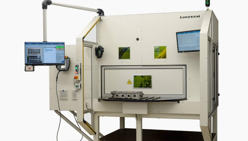
Within the framework of the preparatory study, our LINTECH experts managed to design a comprehensive solution in the form of a sophisticated laser robotic workstation that meets all the above requirements.

Thanks to the high technical level and the high degree of versatility of this solution, we subsequently succeeded in confronting the competition and proceeded to implement the project.

First of all, it is necessary to mention at least briefly the technical equipment of the station:

  • Stäubli TX2-90L robotic arm
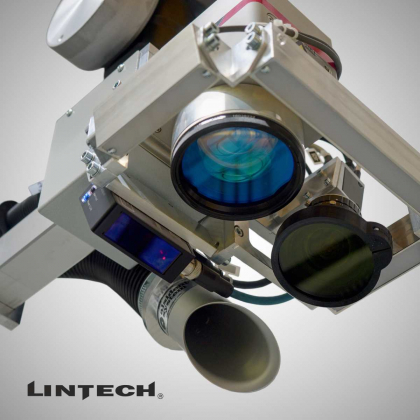
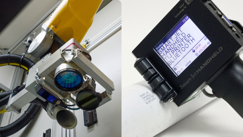
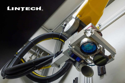
  • Laser system LLS-F70P mounted on the robot’s wrist
  • Cameras
    • The first camera is stationary in the machine and captures the internal position of the rotary table
    • The second camera is together with the laser directly on the robot’s wrist
  • Distance sensor also located directly on the robot’s wrist

The station has been designed to be as simple as possible to operate and can be operated by virtually anyone based on common intuition. At the same time, several control mechanisms have been applied, which immediately detect and in some cases automatically correct any operator errors.

The working sequence of the machine looks like this:

The operator places the part on the turntable in the jig and uses a handheld wireless reader to read the barcode from the attached production order.

Based on the information from the production order, the customized LinMARK user application automatically selects

  • Robot trajectory
  • Reading parameters for the camera on the robot
  • Laser marking job

After turning the table initiated by the operator (loading the part into the machine):

  • First a stationary camera
    • checks whether the part being created matches what was read from the production command
    • detects the position of the product and forwards its position to the robot for correction (within a certain limit range)
  • If OK, the robot moves according to the preset trajectory to the desired location affected by the correction
  • And another inspection is underway
    • The camera on the robot is used to check the position of the original datamatrix code (DMC) and, if necessary, a finer correction of the position of the new marking is made
    • The distance sensor checks whether the laser is at the correct distance from the marking surface (focal length), and corrections are made if necessary
  • If this check is also OK relabels the original DMC code with a new one
    • data to the new DMC will be obtained by the LinMARK application from the parent database, the device also allows manual data entry (currently used for test sets)
  • Finally, the camera on the robot performs a final check of the newly marked DMC and the necessary data is sent to the database.

What is LinMARK?

A key role for the functionality of such a complex device, in which it is necessary to combine the control of several elements, is played by our customized LinMARK application. This is, for the sake of communication with the software laser, is run on the Windows platform.

It is the main user interface of the device and provides convenient work with production data. It displays:

  • PLC states
  • ensures communication and control of the camera system
  • communicates with the robot through trajectories
  • works with a local database in which process information is stored
  • communicates with the parent system

Although it is the main control element of the PLC, the LinMARK application (developed in C#) allows working with complex data structures, which robot trajectories for products whose number is not known in advance undoubtedly are – already because of the need to use a dynamically growing data space.

LinMARK is also a very important component in the case of fault detection – it logs all the work of the equipment and thus allows the analysis of historical events of the machine.

In this case, the graphical interface of the application is designed for use with two monitors:

  • main, control, which displays information about the product, allows to select it and work with production data
  • informative, used to display current images of the camera system, process states and steps

This graphic environment is always designed with an emphasis on the specific positioning of the monitor in relation to the operator and maximizing user-friendliness based on years of experience, modern features known e.g. from mobile phones and customer requirements.

Video

Have we worked together before?
We can help you expand the capabilities of your facility to suit your needs.

More news

Nezávazná poptávka

Odesláním zprávy beru na vědomí zpracování osobních údajů.

Non-binding inquiry

By sending a message, I acknowledge the processing of personal data.